In-depth
Non-contact dimensional measurement: why it matters, technologies and validation
Measuring a part without touching it is not just a matter of convenience. In many industrial applications it is the only way to inspect 100% of production, at line speed, without deforming or damaging the component. But a measurement is only useful if it is reliable: this article looks at why dimensional inspection can be essential, which technologies are used, and how to prove that a measurement system works.
Why measure without contact
Calipers, micrometers and coordinate measuring machines (CMMs) with touch probes remain fundamental tools, but they have limits. They take time, often allow only sample-based checks, and exert a contact force that can alter soft components, such as rubber or plastic gaskets. Optical systems acquire thousands of points in a fraction of a second and integrate in line. They provide numerical data that can be used for statistical process control (SPC), not just a good/bad outcome.
Why dimensional inspection can be essential
Part conformity
The dimensions and tolerances on a drawing are not mere formalities: fit with other components, sealing, assembly and often safety depend on them. A part out of tolerance cannot be used, and the later it is found the more it costs, because a defect discovered at assembly or by the customer costs far more than one rejected at the machine. When dimensional verification is required by the customer or by the specification, inspecting every part is also the most direct way to demonstrate the conformity of the supply.
Monitoring process drift
A machining process does not stay identical over time. Tool wear, a damaged tool or temperature variations gradually shift the dimensions, even while parts are still within tolerance. Measuring every part and recording the values makes it possible to see the trend and intervene, adjusting or replacing the tool, before parts go out of limits. In case of sudden breakage, in-line inspection stops production immediately instead of accumulating a whole box of rejects.
The main technologies
- 2D vision with telecentric optics and collimated illumination. This is the classic solution for profiles, diameters, holes and distances. Telecentric optics remove perspective errors: the part appears the same size even if its distance varies slightly.
- Laser triangulation and profilometers. They measure 2D and 3D profiles, heights and flatness, even on moving parts.
The choice depends on tolerance, part size and material, cycle time and installation environment.
Sistemi 2 Visione srl offers non-contact dimensional measurement solutions for a wide range of applications.
Example 1: gaskets on a glass table
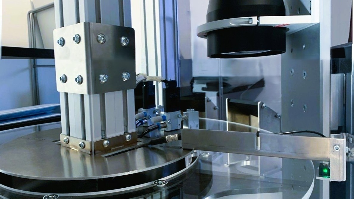
For the dimensional inspection of rubber or plastic gaskets we use a system with telecentric optics and a collimated-light illuminator. The parts rest on a glass table and are backlit. The result is very low optical distortion and no edge effects, that is, none of the halos that shift the apparent outline of the part and distort the measurement.
The station is complete for in-line use. A conveyor belt brings the parts into the machine, a motorised centring device adapts to different diameters, pneumatic air jets separate conforming parts from rejects, and control barriers ensure that no rejected part ends up in the box of conforming ones.
Find out more on the dedicated page
Example 2: machined parts
On machined flanges the same optical principle checks three things at once: presence of chamfers, absence of burrs and measurement of holes. Telecentric optics and collimated light reduce distortion and limit edge effects and reflections. The station is installed in a machining cell and served by a robot.
Find out more on the dedicated page
What really determines accuracy
A common mistake is to confuse resolution with accuracy. Pixel size defines the distinguishable detail, but final accuracy also depends on optical distortion and calibration, type of illumination and edge detection, finish and reflectivity of the part, positioning, vibrations and temperature. The same hole, measured with different illumination, can give values that differ by several hundredths of a millimetre.
Calibration with certified standards
For this reason an optical system must be calibrated with certified standards, for example glass scales or grids, rings and gauge blocks. These standards are traceable to national standards through accredited laboratories (in Italy, the ACCREDIA LAT calibration centres). The measurement thus becomes traceable and comparable over time and across plants, and for certified companies it is also a quality system requirement.
How to validate a dimensional measurement
Having an accurate system is not enough: you must demonstrate that, under real operating conditions, it is suitable for verifying that specific tolerance. The most widely used method is MSA (Measurement System Analysis), a set of statistical techniques that evaluates how much the measurement system contributes to the variability observed on the parts, a technique that originated in the automotive industry and is now used in many sectors.
An MSA study examines in particular:
- accuracy (bias): how far the measurement deviates from the value of a certified standard;
- linearity: whether the error stays constant across the whole measuring range;
- stability: whether the system keeps its performance over time, by periodically measuring a master part;
- repeatability and reproducibility: how much the results vary when the same parts are measured several times, by different operators or with different setups.
These studies are usually complemented by a comparison with a reference, for example a traditional coordinate measuring machine, on a sample of parts.
The reliability of a measurement depends on the system as a whole. To learn more, see the Measurement section of our website or contact us for further information.