In-depth
Road lighting: how light is measured on roads and tunnels
An introduction to photometric quantities, the main European reference standards, and on-site measurement methods.
The context
A well-designed road lighting installation is not simply a "bright" installation: it must ensure that the driver sees obstacles, signs and other road users in time, without glare and without wasting energy. Photometry is the discipline that allows us to verify the correct operation of the lighting system and ensure compliance with the requirements set by current regulations.
Luminance and illuminance: the fundamental quantities
The main photometric quantities are:
- Luminance (cd/m²). This is the quantity that best describes what the driver's eye perceives: the light reflected by a surface, in this case the road surface, toward the observer. It depends on the illumination received, the reflective properties of the pavement itself, and the observation geometry. For example, the same road section, illuminated by a constant installation over time, can produce very different luminance values depending on whether the pavement is dry or wet.
- Illuminance (lux). This is the luminous flux incident on a surface. It is measured with a lux meter and is independent of the reflectance of the road surface. For this reason, standards use it as the main parameter where luminance is of little significance: pedestrian areas, cycle paths, conflict areas such as intersections and roundabouts.
- Veiling luminance (debilitating luminance). This is the light scattered inside the eye that overlaps the retinal image, reducing the contrast of what is being looked at. It is caused by glare from luminaires that are not properly shielded, or by entering a tunnel on a sunny day.
Road surface luminance: parameters and measurement conditions
For roads classified as ME, the standard checks four parameters:
- average pavement luminance (Lm) in predefined areas or sections or in the standard grid;
- overall uniformity (Uo), the ratio between minimum or maximum luminance and average luminance;
- longitudinal uniformity (Ul), along the direction of travel;
Luminance depends on the observer's position, so the standard defines a precise geometry: eye at about 1.5 m above the ground and measurement field placed between 60 m and 120 m away, with a near-glancing view (about 1° of inclination).
Tunnels: different targets for each section
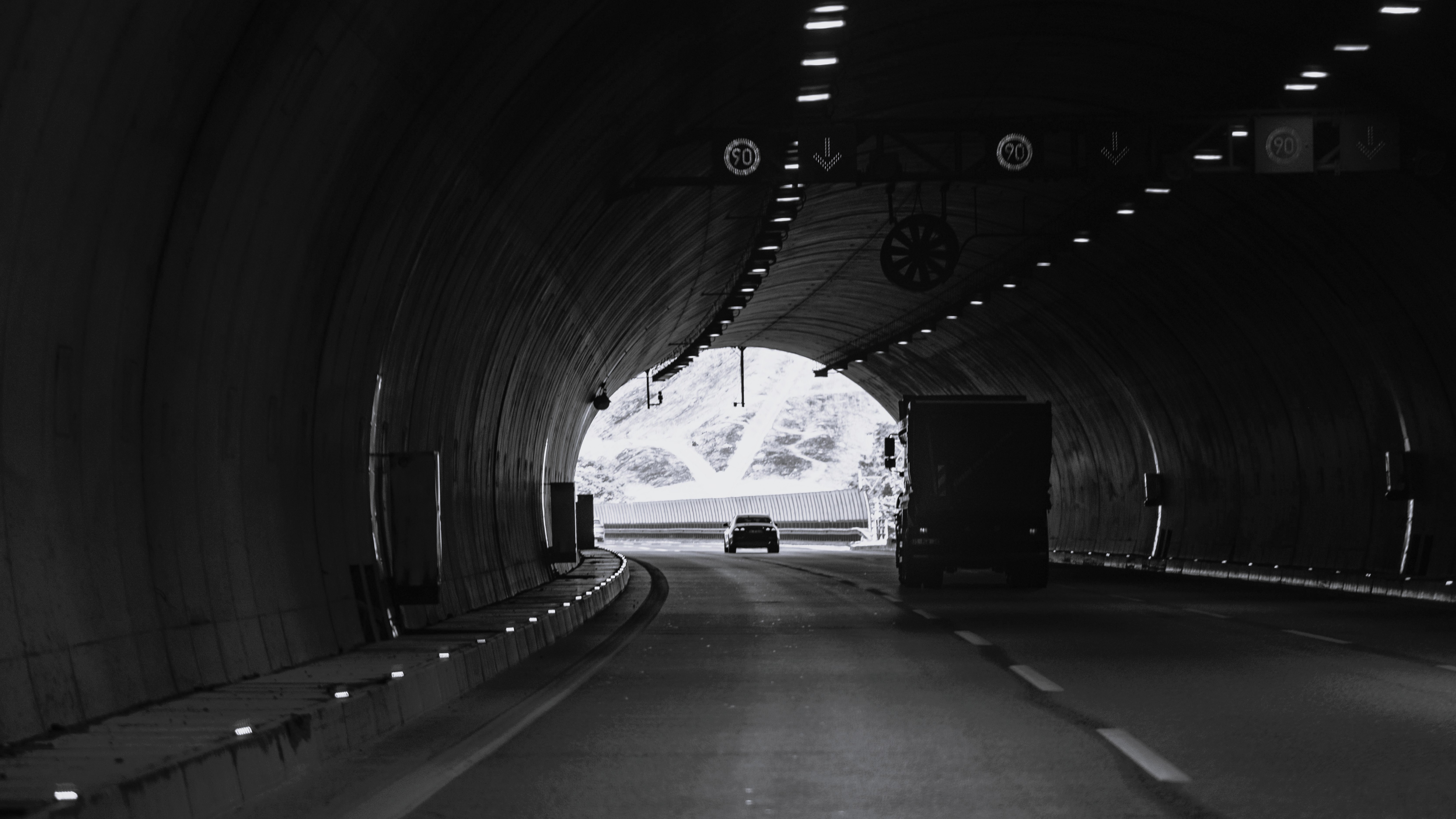
In tunnels, the problem is the eye's adaptation: during the day, the driver arrives from an environment with tens of thousands of cd/m² and must quickly adapt to looking at a much darker area. Lighting is therefore divided into zones, each with its own requirements:
- access zone, where the luminance of the external environment is evaluated (typically the L20 parameter, the average over a 20° visual cone from the adaptation point);
- entry zone, the first internal section, with very high illuminance to reduce the contrast with the outside;
- transition zone, where the level gradually decreases;
- interior zone, with a constant lighting level related to speed and traffic;
- exit zone, where the transition toward the outside is balanced.
In addition to the road surface, the luminance of the walls in the lower band, up to about 2 m in height, is also important: the walls are the background against which the driver sees obstacles, and a dark wall considerably reduces contrast. In tunnels, it is particularly important to check veiling luminance, especially at the entrance.
The European regulatory framework
The main reference for roads is the UNI EN 13201 series:
- UNI EN 13201-2: defines performance requirements and lighting classes: ME (luminance, for motorized traffic roads), CE (illuminance, for conflict areas), and P or S (illuminance for vulnerable users and pedestrian areas).
- UNI EN 13201-3: describes performance calculation.
- UNI EN 13201-4: sets the methods for measuring photometric performance, i.e., how compliance of the installed system with the design is verified in the field.
- UNI EN 13201-5: introduces energy performance indicators.
In Italy, road tunnels are governed by UNI 11095, which addresses tunnel lighting and is in line with the international CIE 88 guide.
For road surface luminance, the CIE reflection tables (the so-called r-tables, with pavement classes R and C) and the average luminance coefficient Q0 are also important: these are the data linking illuminance and luminance.
How it is measured on site
There are two complementary approaches.
Point measurements. Lux meters and luminance meters measure values on a grid of points defined by the standard. This is the classic method: precise, but slow, requires lane closure or traffic slowdown, and only captures a limited portion of the road.
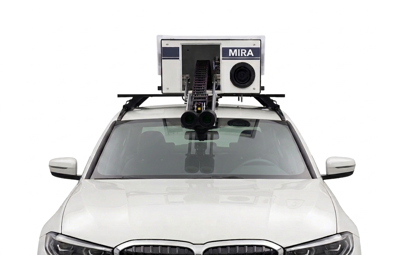
Dynamic measurements. A vehicle equipped with photometric imaging systems acquires luminance while driving at normal speed, without interfering with traffic. Calibrated images (ILMD, imaging luminance measurement devices) make it possible to calculate average luminance, uniformity, and veiling luminance over very long sections, including tunnels where closures are particularly costly. This is the approach used by our MIRA system (Measuring In-motion Road Analyzer).
Periodic measurements
Design calculations are not enough. Lamp and optical aging, pavement condition, and dirt on the luminaires all alter real-world performance over time. Measurement allows us to verify the commissioning of a new installation, plan maintenance, assess energy consumption against regulatory requirements, and, most importantly of all, ensure road safety.
Want to learn more about dynamic photometric measurements? Discover MIRA or contact us for a consultation