In-depth
Road photometric measurements: static or dynamic method?
How does the measurement of luminance and illuminance change when moving from point sampling to motion scanning?
The context
When one needs to verify a road or tunnel lighting installation, the question is not only what to measure (luminance, illuminance, cut-off luminance, uniformity, according to the UNI EN 13201 series), but also how to do it. Today two approaches are compared: the static method, classic and consolidated, and the dynamic method, which brings measurement at traffic speed.
The static method: few points, measured with care
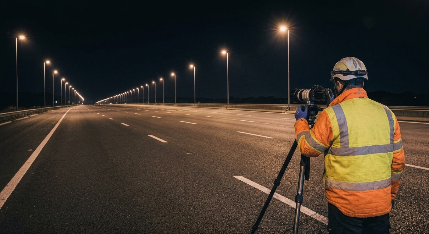
In traditional surveying, a team of operators positions themselves on the roadway at night with luminometers and luxmeters. Measurements are taken in a grid of points along a sample section, as specified by the standard procedures, and values are then transcribed and processed to calculate average luminance, uniformity and other parameters.
The method has an evident advantage: it is well-tested and each point can be measured with great attention. However, limitations become apparent with large-scale installations:
- high times and costs: hours of work for few kilometers, specialized personnel, support vehicles and often more night outings;
- security: operators work on the roadway, at night;
- disruptions to traffic: lane closures, mobile construction sites and permits limit the operational windows;
- partial data: few isolated points on a limited section hardly capture a localized failure or real non-uniformity;
- manual processing: transcription and calculation extend the times and introduce errors difficult to trace;
- no historical record: without georeferenced data it is complicated to compare two measurement campaigns and monitor the degradation of the light flow.
The dynamic method: a vehicle as a mobile laboratory
In dynamic surveying, the measurement moves onto a vehicle. A system such as MIRA (Measuring In-motion Road Analyzer), developed by Sistemi 2 Visione, uses photometric imaging devices (ILMDs, Imaging Luminance Measurement Devices) positioned according to regulations. Each ILMD captures up to 5 images per second while the vehicle travels with traffic. The workflow can be summarized in three stages:
- System configuration: data are archived and organized into measurement campaigns and routes.
- In-motion survey: a GPS receiver starts measurements autonomously near the installation, while the operator remains on board.
- Automatic processing: image processing and generation of the test report, with chromatic luminance heatmaps on the road plane, uniformity and glare analysis, and verification of the lighting class.
The system measures the luminance of the road surface and, in tunnels, that of the walls and disabling luminance in the access zone. Depending on the configuration, it also adds horizontal illuminance, which is useful for checking discrepancies and in areas where luminance cannot be measured.
Comparison between the two methods
| Aspect | Static | Dynamic |
|---|---|---|
| Measurement method | Sample spot checks, few points over a limited area | Continuous scanning of every meter of carriageway |
| Operational speed | Very low: hours for a few kilometres | High: kilometres measured in a few minutes |
| Safety | Operators exposed on the carriageway | Measurement from inside the vehicle |
| Traffic impact | Lane closures and mobile worksites | No disruption |
| Data density | Low, isolated points | High, complete coverage |
| Georeferencing | Not available | Via GPS, with a historical archive |
| Processing | Manual, with possible errors | Automatic |
| Operating costs | High: specialized and support personnel | Optimized by automation |
Why full coverage changes the result
The most important difference is not only speed. Continuous scanning also identifies anomalies affecting one or a few luminaires that a grid of points may completely miss. Every georeferenced measurement then enters the installation database, enabling comparison between different campaigns over time and monitoring the decay of the luminous flux. For a manager, this means planning maintenance based on real data, not estimates.
Accuracy and standards
A dynamic method makes sense only if it is reliable. For this reason, the system must meet the regulatory requirements for sensitivity and dynamics and guarantee, under optimal acquisition conditions, an uncertainty of 5%, with a calibration procedure that ensures metrological traceability. The methodologies comply with UNI and CEN standards, with UNI EN 13201 as the reference for verifying lighting classes.
Which method to choose
The two approaches are complementary. Static surveying remains valid for targeted checks of individual points, while dynamic surveying is the natural choice when extended coverage, repeatability and safety are required: testing of redevelopment works for public administrations, energy audits and long-term monitoring for ESCOs and managers, and validation of calculation models with real post-installation data for design studios.
Want to learn more about dynamic photometric measurements? Discover MIRA or contact us for more information.